 |
Mechanical Compliance of Instrument Tops With Thanks to Bartolini & Bartolini |
| |
Mechanical Compliance of Instrument Tops With Thanks to Bartolini & Bartolini |
If you enjoy the technical side of things, please consider buying my book "Left-brain Lutherie" . Although no longer sold by StewMac, you can buy from LMII, MIMF or directly from me.
It is sometimes popular among usenet writers to declare that "We know nothing about how a guitar really works" and "Only the great masters have control over the creation of extraordinary instruments" and "One must build hundreds of instruments before one can hope to make something that even a good player would want". I suggest that most of the writers of such drivel are abysmally ignorant of existing literature on the subject of musical acoustics in general and guitar acoustics in particular. There is a great deal known and available to anyone with access to the Internet and standard library services. The paper discussed below is a classic example of the type of powerful and applicable material that exists.
One of the most eclectic papers written about the acoustical properties of guitars is by W. and P. A. Bartolini in Issue #6 of the Journal of Guitar Acoustics. Among the many fundamental acoustical and mechanical properties measured on a variety of guitar tops was mechanical compliance. For further details, I recommend reading the article itself.
In all honesty, I hadn't appreciated the significance of this measurement until Ross Gutmeier, an East Coast classical guitar builder, told me that he had had success using this approach in building his instruments. A useful discussion ensued and I applied the compliance measuring concept to building my ukuleles and guitars. After an initial trial and error period, a set of useful measurements were achieved, although fine tuning is still going on. Hey, it's lutherie, right? In this webpage, I will describe the simple compliance measuring setup that I use and show it in operation. I will also give several sets of compliance measurements for successful instruments that I've built as a general guide for the reader.
But what is compliance? Compliance is a measure of the deformation of a body (for example a plate) under load. If a weight is gently placed on the center of a guitar top, the deformation of the top is the mechanical compliance relative to that particular weight and its placement. By measuring the compliance of the top, we can obtain a quantitative estimate of its mechanical stiffness. So, if you had a guitar which sounded great and whose top hadn't caved in as a result of string tension and bridge torquing, you could make a map of the mechanical compliance of the top. This map would then be a powerful building tool, since one could aim toward reproducing the compliance map by brace carving and top thinning.
Let's first look at an overview picture of the process. Then we'll look at the actual pieces of the apparatus. Finally, we'll return to the measurement process and look at some data.
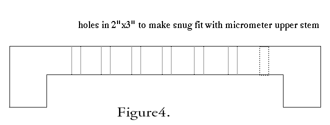
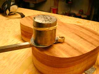
The first picture (Figure 1) shows the basics of the process: an instrument body with the top but not the back attached to the sides; to the left a sort of lever arm thing with a little platform and ring on the end of it; and to the right a U-shaped wooden frame with holes the length of it and a dial micrometer in one of the holes. Missing is the weight that sits on the platform and causes the deformation.

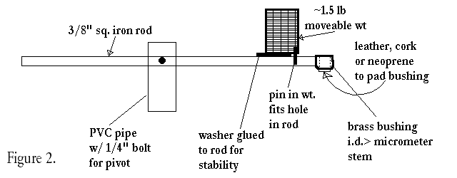
If you think it's pretty simple, then I have achieved my purpose. You can build this setup in an hour or two and have the whole business cost only a little more than the cost of the dial micrometer itself. Any shop has scraps from earlier projects lying about and this is mostly what I used. Let's look at the first drawing (Figure 2) in a little more detail.
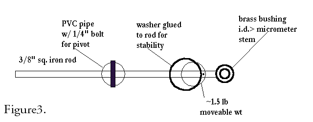
 The pivot axis for the lever arm (Figure 5) is simply a 1/4" bolt through a 2" diameter length of PVC pipe,
with channels cut in the upper portion of the pipe to allow the lever arm to move laterally somewhat.
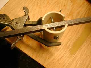
I hold the PVC pipe with a laboratory clamp, a souvenir of my former chemistry days, but I'm sure that other options will come to you if such a device isn't readily available to you.
The pivot axis for the lever arm (Figure 5) is simply a 1/4" bolt through a 2" diameter length of PVC pipe,
with channels cut in the upper portion of the pipe to allow the lever arm to move laterally somewhat.
I hold the PVC pipe with a laboratory clamp, a souvenir of my former chemistry days, but I'm sure that other options will come to you if such a device isn't readily available to you.
The weight used (shown on the stem washer, Figure 6) is a piece of ca. 2" diameter by 2" long steel rod, weighing about 1.5 lbs. This weight is sufficient for ukuleles and classical guitars but I would double it for steel stringed instruments in order to get sufficient deflections from the dial micrometer. At the beginning of this process I was concerned about the exact placement of the weight on the washer platform.
O.K., let's make some measurements. See Figure 7. In preparation for the eagerly anticipated event, choose a flat, relatively clean work surface for the measuring device and the top-and-sides portion of the instrument. A chair of such a height that one is eye level with the dial micrometer when it is in use will be very convenient. You should also have your small palm planes, 80 grit sandpaper swatches and so forth handy for removing brace material. You may have roughed out the brace shapes before the top was attached to the sides, but should have intentionally kept them ~ twice as large as you think they should be in the final instrument.
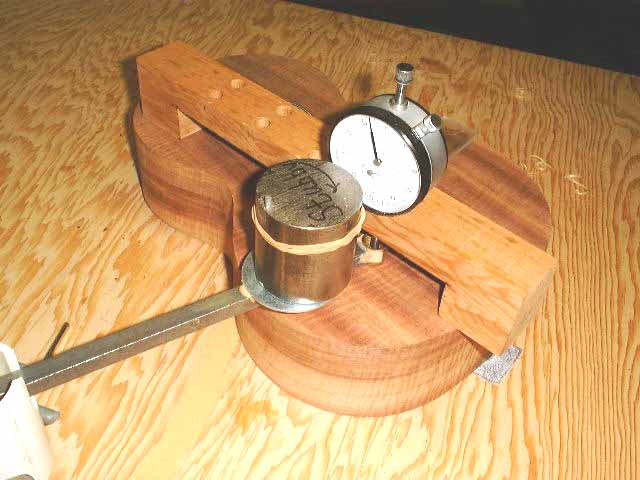
Raise the height of the stem/lever arm holder so that the bushing undersurface is flat on the top of the instrument and the stem/lever arm is parallel to the surface of the top. You may also have to rotate the holder laterally slightly to achieve correct vertical alignment. The placement of the stem/lever arm holder on the table top may also require a little thought. I find it easier to move the instrument around and leave the holder fixed, but there is no wrong way as long as the measurements are made consistently.
Place the lever arm in the center of the lower bout as a starting place. Make sure that the lever arm is not binding on the PVC holder or 1/4" bolt and can move freely. Adjust the wooden frame so that one end sits on an edge (see above, Figure 7). Choose the nearest hole on the frame and insert the dial micrometer. Move the frame so that the micrometer tip is in the center of the bronze bushing. Gently place the weight on the washer platform. Press on the weight gently several times and note the micrometer reading. Remove the weight and note the reading again. Repeat until you feel that you have a satisfactory measurement. Congratulations! You've made your first mechanical compliance measurement.
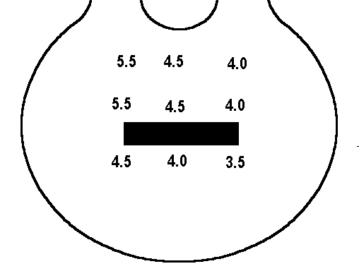
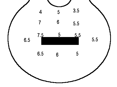
Figure 8, above, shows a set of mechanical compliance measurements for a recently built concert ukulele of mine. The numbers are in thousandths of an inch and are for the weight/lever arm combination that I use (1.37 lbs or 620 grams at the end of the lever arm with the weight on the platform). If your system is different (for example by using a heavier weight) you would need to normalize the data in Figure 8 by dividing the deflection by the tongue weight I used and then multiplying the resulting value by the tongue weight for your system. Figure 9, below shows analogous numbers for a classical guitar that I built which turned out well also.
Note that I have made the mechanical compliance measurements asymmetrical. This is done in order to reduce the effect of the second fundamental on tonal quality. Careful scanning of that frequency region should now yield a doublet rather than a single peak as have would resulted from symmetrical mechanical compliance. Additionally, the first top resonance was measured at about 500 Hz. It is entirely possible that you could have a different resonance value even if the mechanical measurements were the same. Why? If you used topwood and braces that had a higher stiffness to density ratio than mine, then for the same mechanical stiffness the top would weigh less and the resulting frequency would be somewhat higher. Conversely a less stiff system would have a lower frequency because of its greater weight. See Benade, "Fundamentals of Musical Acoustics", pp. 136-140 for further discussion.
If you like the types of problems discussed in this page, please consider being a participant in the LEFTBRAINLUTHERIE mailing-list.
The list is now being managed by Australian luthier Jeremy Locke and is available at:
leftbrainluthiers@yahoogroups.com
I enjoy writing these pages and hope that they are interesting and useful to the reader. I'm slowing down in my building at this time and still need to generate some income in order to continue to expand this website with more useful articles. If this page was helpful to you and you would like to make a $5.00 donation in order to have more pages like it, please use the donation button below. Thank you.
To explore more of the website, please refer to the Sitemap and Search Engine