 |
Simple Experiments, Part 2: How Higher Modes Compare with fdisk
|
| |
Simple Experiments, Part 2: How Higher Modes Compare with fdisk
|
If you enjoy the technical side of things, please consider buying my book "Left-brain Lutherie" . Although no longer sold by StewMac, you can buy from LMII, MIMF or directly from me.
In this part of the experiment series, we continue along with higher frequency measurements of the same wooden disks glued onto PVC pipe that we used in Simple Experiments, Part 1.
We're not trying for Nobel prizes here, just trying a simple progression of observations to give the reader some sense of how the measured physical properties of the wood interact with one another.
In this series of experiments, we go to successively higher frequencies to explore the relationship between the lowest large resonant frequency and the next three above it. I've only gone so far as to measure the next three because these are most commonly discussed in the guitar literature and seem to me to be within the realm of alteration by the builder.
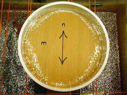
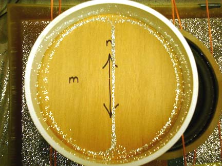
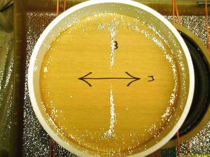
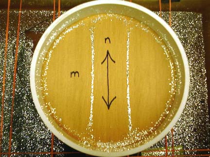
Modes are generally designated by two numbers; within formulae we use letters to designate cross-grain ( m ) and parallel to grain ( n ) resonances. Figure 1 shows a 0,0 ( m,n ) mode where the whole top is moving up and down at its particular resonant frequency. The arrow on the wood points parallel to grain. In Figure 2, we see a 1,0 mode; Figure 3 shows a 0,1 mode and Figure 4 shows a 2,0 mode.
 |
 |
|
Figure 1. 0,0 mode of red cedar disk |
Figure 2. 1,0 mode of red cedar disk |
 |
 |
|
Figure3. 0,1 mode of red cedar disk |
Figure 4. 2,0 mode of red cedar disk |
Modes are excited the most when we direct energy in the form of a tap or vibration pulse to the center of the mode. When such energy is directed at a node of that particular mode, it will be difficult to make the mode appear. Note that we have placed the speaker directly under the plate in Figures 1 and 4, while the speaker only covers half the disk in Figures 2 and 3.
 |
|
Figure 5. Red line is FFT of taps at "m" in Figs 1-4; black line is FFT of taps at "n" |
Figure 5. shows two different Fourier transforms of tap tones taken from the cedar disk. The Red line shows the transform of a tap tone taken at "m" on the disk, while the Black line shows the transform of a tap tone taken at "n" on the disk. As expected, the Red line shows those modes where the "m" is either in the center or not too far from the center of the mode: 0,0 ; 1,0 ; and 2,0 are most prominant. Conversely, the Black line shows the 0,0 and 0,1 modes most clearly. Let's now look at the rest of the disk data in a little more detail.
To save switching back and forth, I've included the data from Simple Experiment 1 in Table 1 below:
|
Table 1. A Review of Data Collected and Calculated in Experiment 1 |
|
Ex, psi |
Ey, psi |
Ex/Ey |
DiskCompl, in |
Edisk, calc |
fcalc Hz |
|
|
plate#1, Red cedar |
6.32E+05 |
2.93E+04 |
22 |
0.024 |
2.39E+05 |
259 |
|
plate#2, Redwood |
1.26E+06 |
1.17E+05 |
11 |
0.012 |
4.77E+05 |
325 |
|
plate#3, Douglas fir |
2.43E+06 |
1.93E+05 |
13 |
0.0082 |
7.20E+05 |
345 |
First let's look at the resonant frequencies for each mode and each disk in Table 2.
|
Table 2. Modal Frequencies for each Disk |
| modal types (m,n) -> | 0,0 | 1,0 | 2,0 | 0,1 |
| plate#1, Red cedar | 235 | 345 | 490 | 601 |
| plate#2, Redwood | 295 | 433 | 622 | 758 |
| plate#3, Douglas fir | 327 | 464 | 690 | 807 |
Now let's look at the ratios of each of the higher modal frequencies to the 0,0 frequency:
|
Table 3. Ratios of Higher Modal Frequencies to the 0,0 Frequency |
| modal ratios -> | 0,0 / 0,0 | 1,0 / 0,0 | 2,0 / 0,0 | 0,1 / 0,0 |
| plate#1, Red cedar | 1 | 1.47 | 2.09 | 2.56 |
| plate#2, Redwood | 1 | 1.47 | 2.11 | 2.57 |
| plate#3, Douglas fir | 1 | 1.42 | 2.11 | 2.47 |
| Average | - | 1.45 | 2.10 | 2.53 |
I regard these results as particularly interesting. In spite of the fact that the sample range of Ex is four-fold and that of Ey is nearly seven-fold, all the modal ratios within the same column are within 2-3% of each other!
Based on this miniscule amount of data above, I suggest that: 1. in the absence of bracing and a bridge, and 2. if the top is of uniform thickness that the above ratios will generally hold for the lower bout of a guitar family instrument .
If we add bracing parallel to grain, we will be increasing stiffness and the frequency of the 0,1 mode while adding mass and decreasing the frequency of the 1,0 and 2,0 modes. Putting on the bridge would seem to have the opposite effect. So parallel to grain bracing enhances the orthotropic nature of the top. In that the few amplitude vs. frequency spectra available in the literature show a reversal of the order of the 0,1 and 2,0 modes, the bridge must have a considerable effect by both increasing cross grain stiffness and adding mass to the parallel to grain dynamic properties.
If we begin to splay the braces, we will tend to bring the frequencies closer together. Ladder bracing is of course the other end member in opposition to parallel to grain bracing. In between the ladder and parallel to grain bracing systems are variants of the parallel system with a variety of diagonal members, some of which occur only on one side, others which are symmetrical. Lattice bracing, a diamond-shaped mesh of braces, offers the option of bringing the two frequency groupings together to make the top more isotropic depending on the angle of the lattice corners. If greater strength is achieved with less weight, then the fundamentals would be lowered relative to a less "efficient" bracing. I have no idea at this time whether an "isotropic" top is "better" than an orthotropic one.
After bracing, the next topic of study would be what distribution of frequencies produce what sound characteristics in a finished instrument. I think that we all appreciate that there is no single "best" sound for an instrument. I think also that many of us would like more control over the final product we make. If there is a way to predict what spectra would exist as a result of varying the bracing patterns, and how these spectra would effect final tone, that would be a wonderful collection of knowledge to share...
(More data, references and discussion needed at this point regarding the ratios of various modes in successful instruments...DCH 3/27/2002)
If you like the types of problems discussed in this page, please consider being a participant in the LEFTBRAINLUTHERIE mailing-list.
The list is now being managed by Australian luthier Jeremy Locke and is available at:
leftbrainluthiers@yahoogroups.com
To explore more of the website, please refer to the Sitemap and Search Engine